
Power Factor Formula (PF = kW ÷ kVA) with Examples
Quick answer: What is power factor? #
What is power factor? It is the ratio of real power to apparent power: PF = kW ÷ kVA (the power factor formula). Example: 80 kW / 100 kVA = 0.80 PF. For a consuming load, PF magnitude is at most 1 (leading/lagging reported separately). Instant convert: kW to kVA calculator.
Introduction #
Instant answer: True PF = kW ÷ kVA (this is the power factor formula / pf formula). For a consuming load, 80 kW / 100 kVA = 0.80 PF; the same 80 kW at a verified 0.95 true PF corresponds to ≈84.2 kVA. Only for a sinusoidal single-frequency case does PF reduce to the displacement relation cos θ.
Open kW to kVA — 80 kW @ 0.80 → kVAR correction 100 kW · 0.80→0.95 →
The electrical power factor formula is PF = kW ÷ kVA (real power divided by apparent power). Use quantities measured under the same definition, boundary, and interval. In nonsinusoidal or unbalanced systems, true PF and fundamental-frequency displacement PF are different measurements; capacitor correction calculations normally act on fundamental reactive power and do not automatically correct distortion. IEEE 1459-2025 defines power quantities for sinusoidal, nonsinusoidal, balanced, and unbalanced conditions. This page is for electrical / industrial power systems—not firearms or USPSA “power factor.”
For an instant power factor calculator workflow, open the kW to kVA calculator (enter kW and PF → apparent power) or the kW to kVAR / power factor correction calculator (enter kW + PF → capacitor bank ΔkVAR). This guide owns the formula and examples; those two tools own the instant conversions.
| Intent | Open |
|---|---|
| Convert kW ↔ kVA at a known PF | kW to kVA calculator |
| Size capacitors / PF correction (target PF → ΔkVAR) | kW to kVAR calculator |
| Learn PF = kW ÷ kVA with worked examples | Stay on this page |
The Power Factor Formula #
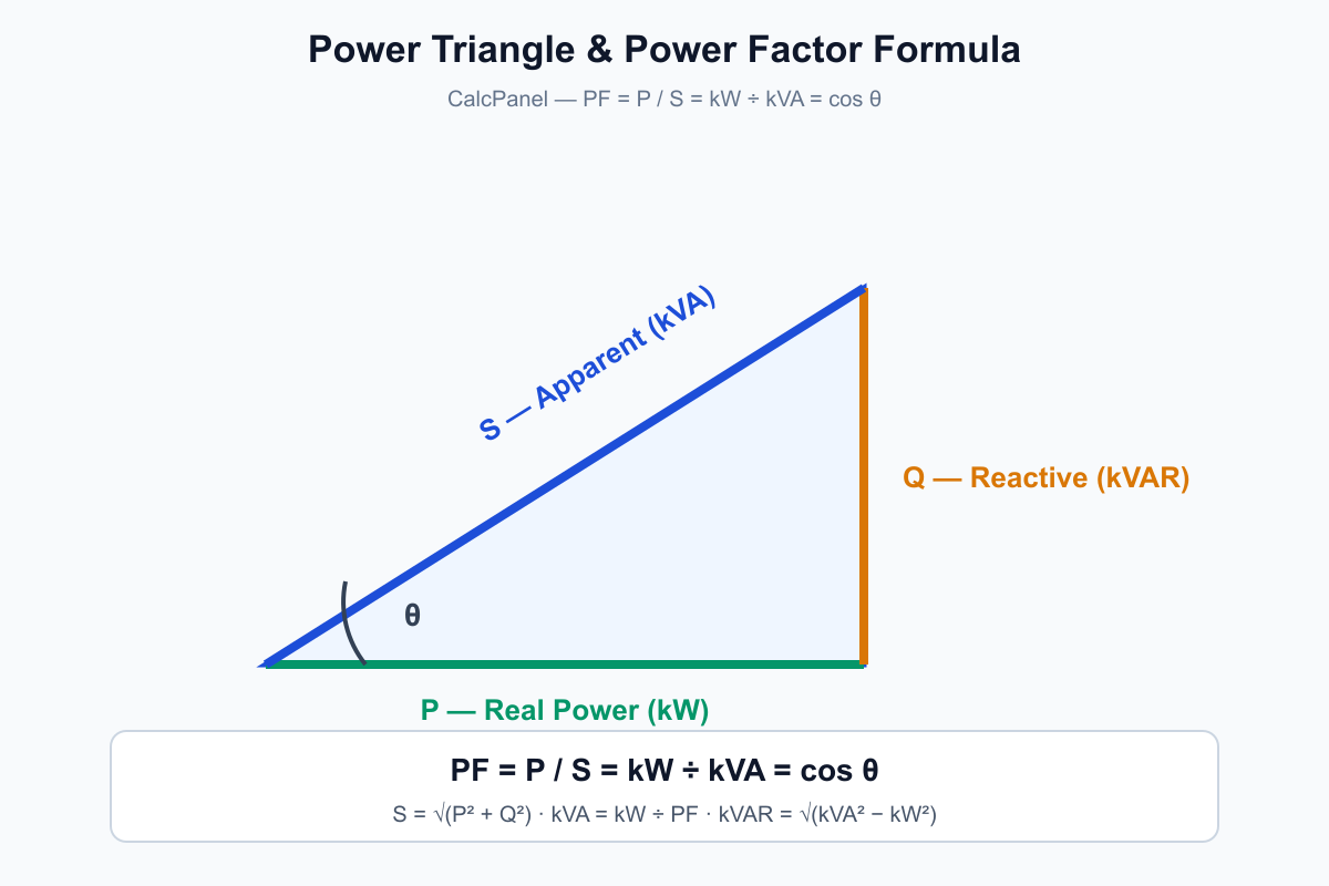
PF = kW ÷ kVA
| Need | Formula |
|---|---|
| Power factor | PF = kW ÷ kVA |
| Apparent power | kVA = kW ÷ PF |
| Real power | kW = kVA × PF |
| Reactive power, sinusoidal triangle | kVAR = √(kVA² − kW²) |
Three-phase shortcut (balanced, sinusoidal, simultaneous RMS values):
PF = kW ÷ (V × I × √3 ÷ 1000)
where V is line-to-line volts and I is line amps.
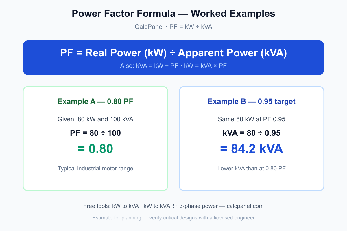
Worked example (0.80 PF): 80 kW and 100 kVA → PF = 80 ÷ 100 = 0.80. At a verified 0.95 PF, the same 80 kW corresponds to 84.2 kVA (80 ÷ 0.95)—run it in the kW to kVA calculator.
Jump to tools: kW to kVA · 3-Phase Power · kW to kVAR. More 3-phase numeric drills: 3 Phase Power Formula & Examples.
Who This Guide Is For #
This guide is written for:
- Electrical engineers designing and analyzing power systems
- Facility and energy managers optimizing energy costs and system efficiency
- Industrial system designers selecting and sizing electrical equipment
- Maintenance professionals troubleshooting power quality issues
- Students and learners studying electrical engineering fundamentals
What This Guide Covers #
In this guide, you will learn:
- What power factor is and why it matters
- Power factor formulas (single-phase and three-phase)
- How power factor is measured
- Utility power factor penalties
- Power factor correction methods
What is Power Factor? #
Power factor (PF) is the ratio of real power (kW) to apparent power (kVA) at a defined measurement boundary. For an ordinary consuming load its magnitude is between 0 and 1, with leading or lagging direction reported separately when relevant. Unity PF is not the same as 100% energy efficiency: equipment can have PF = 1 while still dissipating real-power losses. Whether a value is acceptable depends on the equipment, system limits, tariff, measurement definition, and operating state—not a universal “good/poor” band.
The core relationship stays PF = kW ÷ kVA—see the formula table above for rearrangements and the three-phase meter form.
Understanding Real Power vs Apparent Power #
To understand power factor, you need to distinguish between two types of power:
Real Power (kW) #
Real power, measured in kilowatts (kW), is the actual power that performs useful work - such as turning motors, producing heat, or powering lights. This is the power you pay for on your electricity bill.
Apparent Power (kVA) #
Apparent power, measured in kilovolt-amperes (kVA), is the total power that flows through the system. It includes both real power and reactive power (the power that oscillates back and forth but doesn't do useful work).
Reactive Power (kVAR) #
Reactive power, measured in kilovolt-amperes reactive (kVAR), is the power that oscillates between the source and load but doesn't perform useful work. It's necessary for magnetic fields in motors and transformers but increases current flow without contributing to actual work.
Reactive power formula (kVAR / Q) #
For sinusoidal quantities with compatible definitions, the reactive power formula follows the power triangle (the same screening math used by the kW to kVAR calculator):
| Need | Reactive power formula |
|---|---|
| From kVA and kW | kVAR = √(kVA² − kW²) |
| From kW and PF | kVAR = kW × tan(arccos PF) |
| From kVA and PF | kVAR = kVA × sin(arccos PF) |
| Three-phase (balanced, sinusoidal) | kVAR = √3 × V × I × sin(θ) ÷ 1000 with θ = arccos(displacement PF) |
Worked example: 100 kW at PF 0.80 → kVA = 100 ÷ 0.80 = 125 kVA → kVAR = √(125² − 100²) = 75 kVAR. Correction from 0.80 → 0.95: use ΔkVAR = Q₁ − Q₂ (about 42 kVAR for 100 kW)—run it in the kW to kVAR / reactive power calculator.
Deep link: power factor formula · 3 Phase Power Formula & Examples
The Power Triangle #
The relationship between real power (kW), apparent power (kVA), and reactive power (kVAR) can be visualized as a right triangle:
        kVA (hypotenuse)
        /|
       / |
      /  | kVAR
     /   |
    /____|
    kW
Formula for the sinusoidal power triangle: kVA² = kW² + kVAR². With distortion/unbalance, the selected standard or analyzer may report additional/nonactive components, so this identity is not a universal wiring check.
Why Power Factor Matters #
Power factor has significant implications for industrial operations:
1. Energy Costs #
Some utility tariffs charge for kVA demand, reactive demand/energy, or apply a PF adjustment. The trigger, averaging interval, leading/lagging treatment, ratchet, and eligible customer class vary. Where the same real power is delivered at lower PF, current and apparent power are higher, which can increase:
- Line losses (I²R losses)
- Voltage drop
- Equipment heating
- Overall system inefficiency
Example: A facility with 100 kW load at 0.70 true PF corresponds to about 143 kVA, while the same load at 0.95 true PF corresponds to about 105 kVA. Whether either value changes the bill depends on the actual tariff and billing interval.
2. Equipment Sizing #
Low power factor requires larger transformers, cables, and circuit breakers to handle the increased current. This means:
- Higher initial equipment costs
- Larger installation space requirements
- Reduced system capacity
Example: A 100 kVA transformer can only deliver 80 kW at 0.8 power factor, but 90 kW at 0.9 power factor.
3. System Capacity #
A poor power factor reduces the effective capacity of your electrical system. For example, a 100 kVA transformer can only deliver 80 kW at 0.8 power factor, but 90 kW at 0.9 power factor.
Power Factor Formulas #
Single-Phase Power Factor Formula #
For single-phase systems, using simultaneous RMS voltage/current and real power:
Power Factor = kW ÷ kVA
Or using voltage and current:
Power Factor = (kW × 1000) ÷ (Voltage × Current)
Example: If you have 80 kW and 100 kVA, PF = 80 ÷ 100 = 0.8
Three-Phase Power Factor Formula #
For searches like 3 phase power factor / three-phase power factor formula, use this balanced shortcut with simultaneous line-to-line RMS voltage and representative line RMS current (includes √3):
Power Factor = (kW × 1000) ÷ (Voltage × Current × √3)
Or rearranged (same identity as the head formula):
Power Factor = kW ÷ kVA
Where kVA = (Voltage × Current × √3) ÷ 1000
Worked example (3 phase power factor): 100 kW, 480 V line-to-line, 150 A line → PF = 100,000 ÷ (480 × 150 × 1.732) = 0.80. Instant check: 3 phase power calculator or measure path How to Measure Power Factor in 3-Phase Systems.
Example: In industrial three-phase power systems, power factor is closely related to load characteristics and efficiency. If you are not familiar with how three-phase systems work, see our Three-Phase Power Guide for a system-level explanation.
For full worked examples with √3, line vs phase voltage, and multi-load scenarios, see our dedicated 3 Phase Power Formula & Examples guide—this page keeps the PF formula summary only.
What Causes Low Power Factor? #
Several factors contribute to poor power factor in industrial settings:
Inductive Loads #
- Motors: Induction motors create lagging power factor, especially when underloaded. For motor-group kVAR screening with HP/kW bands and worked examples, use the Power factor for industrial motors sizing scenario.
- Transformers: Transformers require magnetizing current, creating reactive power
- Solenoids and coils: Electromagnetic devices create inductive reactance
Load Characteristics #
- Underloaded motors: Motors running below their rated capacity have lower power factor
- Fluorescent lighting: Older ballasts can cause poor power factor
- Welding equipment: Arc welders typically have very low power factor (0.3-0.5)
- Variable Frequency Drives: Some VFDs can cause harmonic distortion affecting power factor. For harmonic-aware correction planning, see the Power factor for VFD harmonics scenario and Harmonics in Power Factor Correction guide.
Power Factor Depends on the Actual Operating Point #
Do not assign a design PF solely from equipment type. Motor PF changes with model and shaft load; LED drivers, welders, VFDs, UPSs, and other electronic loads also differ in displacement PF and current distortion. Use nameplate/OEM data for planning and a compatible power analyzer for an operating installation. If no verified PF is available, any assumed value is a sensitivity case—not an equipment rating.
How to Calculate Power Factor #
How do you calculate power factor? Use these steps:
- Measure or look up real power P in kW (wattmeter / bill / analyzer).
- Measure apparent power S in kVA using a definition compatible with the real-power measurement. The balanced sinusoidal shortcuts are S = √3 × VLL × IL ÷ 1000 for three phase and S = V × I ÷ 1000 for single phase.
- Apply the power factor formula: PF = kW ÷ kVA (also written PF = P ÷ S).
- Optional: rearrange for sizing — kVA = kW ÷ PF — or open the kW to kVA calculator for an instant result.
Power Factor = kW ÷ kVA
For balanced sinusoidal three-phase systems from simultaneous line quantities:
Power Factor = kW ÷ (Voltage × Current × √3 ÷ 1000)
Why multiply by 1.73 (√3)? Under the balanced three-phase assumptions, √3 converts line-to-line voltage and line current into total VA. Omitting it under those assumptions understates kVA and overstates PF; adding it does not make a one-channel method valid for an unbalanced or distorted system.
Example: If you have 80 kW and 100 kVA, PF = 80 ÷ 100 = 0.8
Three-phase from measurements: The √3 shortcut is appropriate only when the balanced assumptions hold and voltage, current, and kW are simultaneous. For unbalanced or distorted systems, configure a multi-channel analyzer for the actual 3-wire/4-wire circuit and use its total P and compatible total S. For multiple sinusoidal loads, add coincident signed P and Q first, then calculate S = √(P² + Q²); do not average PF values or sum individual kVA magnitudes as a general rule.
Common mistakes: Using phase voltage in a line-voltage shortcut, omitting √3 in a balanced line-quantity calculation, mixing nonsimultaneous readings, or averaging phase/load PF values instead of combining compatible total power quantities. See How to Measure Power Factor and the 3-phase measurement guide for field procedures.
How to Measure Power Factor #
Using Clamp Meter and Voltmeter #
- Measure line voltage (V)
- Measure line current (A)
- Measure real power (kW) using a wattmeter
- For a balanced sinusoidal system, calculate PF = (kW × 1000) ÷ (VLL × IL × √3); otherwise use the correctly configured analyzer's total P/S
Using Power Analyzer #
Power analyzers provide direct power factor readings along with:
- Real power (kW)
- Apparent power (kVA)
- Reactive power (kVAR)
- Power factor
- Harmonic content
Measurement Best Practices #
- Measure under normal operating conditions
- Take multiple readings over time to account for load variations
- Measure at the point of common coupling (PCC)
- Consider load diversity and peak demand periods
For detailed step-by-step instructions on measuring power factor in three-phase systems, including tool selection, wiring methods, troubleshooting, and handling unbalanced loads, see our guide on How to Measure Power Factor in 3-Phase Systems.
Utility Power Factor Penalties #
Power-factor billing is tariff-specific. A utility may bill kVA demand, kVAR/kVARh, adjust measured kW demand, apply a ratchet, distinguish leading from lagging operation, or impose no PF charge on a given customer class. The U.S. Department of Energy likewise lists PF adjustments and direct reactive charges as possible—not universal—bill components. Read the current tariff and use the utility meter's definition and interval before estimating savings. For the decision path, see Power Factor Penalty: Utility Rules and Cost Impact.
Power Factor Correction Methods #
Improving power factor can reduce energy costs and increase system capacity. Here are the most effective methods:
1. Power Factor Correction Capacitors #
The most common solution is installing power factor correction (PFC) capacitors. These devices supply reactive power locally, reducing the reactive power drawn from the utility. In systems with VFDs, rectifiers, or other nonlinear loads, harmonic distortion can cause capacitor resonance and equipment damage. See our guide on Harmonics in Power Factor Correction for when to use detuned capacitors and how to avoid resonance.
Types:
- Fixed Capacitors: For constant loads
- Automatic Capacitors: For varying loads with automatic switching
- Location: Can be installed at the main panel or near large motors
2. Synchronous Motors #
Synchronous motors can be operated at leading power factor, effectively acting as power factor correction devices while performing their primary function.
3. Optimize Motor Loading #
Compare the motor's actual load point with its manufacturer performance data. Underloading often reduces induction-motor PF, but there is no universal loading percentage that guarantees a particular value.
4. Replace Old Equipment #
Do not assume newer equipment has better true PF. Compare the actual product's input PF, displacement PF, harmonic current, efficiency, and operating profile before replacement.
Calculating Required Capacitor Size #
To determine the capacitor size needed for power factor correction, use the following formula:
kVAR = kW × (tan θ₁ - tan θ₂)
Where:
- θ₁ = angle of current power factor
- θ₂ = angle of desired power factor
For complete step-by-step capacitor sizing calculations, selection criteria, installation considerations, and real-world examples, see our comprehensive guide on Capacitor Bank Sizing for Power Factor Correction.
Benefits of Power Factor Correction #
- Potential bill reduction: only where the tariff charges for the affected kVA/kvar/PF interval
- Upstream capacity relief: correction can reduce current in conductors and transformers upstream of the correction point
- Voltage/loss change: may reduce voltage drop and I²R loss on the affected upstream path
- Important boundary: capacitors do not reduce real energy used by the load and can create leading PF, switching transients, or harmonic resonance if misapplied
Power Factor in Single-Phase vs Three-Phase Systems #
Power factor applies to both single-phase and three-phase systems, but the calculation methods differ:
| Aspect | Single-Phase | Three-Phase |
|---|---|---|
| Balanced sinusoidal shortcut | PF = (kW × 1000) ÷ (V × I) | PF = (kW × 1000) ÷ (VLL × IL × √3) |
| Voltage | Phase voltage | Line voltage |
| Current | Phase current | Line current |
| Application | Residential, small commercial | Industrial, large commercial |
Important: PF remains P/S, but the shortcut used to obtain S depends on system configuration and assumptions. For unbalanced or nonsinusoidal systems, use a compatible measurement definition rather than treating √3 as the only difference.
Application scenarios (by load type) #
This guide covers formulas and methods site-wide. For load-specific screening with tables, scale examples, and calculator chains, use these Tier S deployment scenarios on CalcPanel:
- Power factor for industrial motors — 3-phase induction motor kVAR bands, HP roll-up, and capacitor screening for pump/fan/compressor groups.
- Factory power factor optimization — whole-plant PF roll-up by load class, penalty screening, and automatic bank step planning.
- Power factor for VFD harmonics — detuned capacitor and THD-aware correction when VFD share is high on a feeder or plant bus.
Each scenario links back to this guide for formulas; start here for theory, then open the scenario that matches your dominant load type.
Related Tools #
- kW to kVAR Calculator: Calculate reactive power from kW and PF—the primary tool for capacitor bank sizing and correction planning
- kW to kVA Calculator: Convert between kW and kVA using power factor and determine apparent power requirements
- 3-Phase Power Calculator: Calculate 3-phase kW, kVA, and current with power factor for industrial applications
- Factory Load Calculator: Calculate total factory electrical load including power factor considerations
- Transformer Size Calculator: Size transformers accounting for power factor and load characteristics
Related Articles #
- 3 Phase Power Formula & Examples: Worked √3 examples for kW, kVA, and power factor in balanced three-phase systems
- How to Measure Power Factor in 3-Phase Systems: Step-by-step measurement with power analyzers, clamp meters, and troubleshooting
- Power Factor Penalty: Utility Rules and Cost Impact: Penalty thresholds, calculation methods, cost examples, and avoidance strategies
- Capacitor Bank Sizing for Power Factor Correction: kVAR sizing, selection criteria, and installation considerations
- Harmonics in Power Factor Correction: Detuned capacitor banks, resonance risks, and THD in PFC design
- 3-Phase Power Explained: System-level overview of three-phase power and how PF fits in
- kW vs kVA: Understanding the Difference: How power factor links real and apparent power
Frequently Asked Questions #
What is the reactive power formula?
The core reactive power formula is kVAR = √(kVA² − kW²), or kVAR = kW × tan(arccos PF). Three-phase: kVAR = √3 × V × I × sin(θ) ÷ 1000. Example: 100 kW at PF 0.80 → 75 kVAR. Instant path: kW to kVAR calculator · section Reactive power formula.
What is the formula for calculating reactive power?
Same identities: find kVA = kW ÷ PF, then kVAR = √(kVA² − kW²). For capacitor banks between two PF targets use ΔkVAR = Q₁ − Q₂. See reactive power formula.
What is the power factor formula?
The general true power factor formula (pf formula) is PF = kW ÷ kVA using compatible measurements. For a sinusoidal power triangle, kVA = kW ÷ PF, kW = kVA × PF, and kVAR = √(kVA² − kW²). The balanced three-phase shortcut is PF = kW ÷ (VLL × IL × √3 ÷ 1000); use a correctly configured analyzer for distorted or unbalanced systems.
What is the pf formula?
pf formula is the short label for the same identity: PF = kW ÷ kVA. Example: 80 kW and 100 kVA → 0.80. Jump to The Power Factor Formula or convert instantly with the kW to kVA calculator.
What is the 3 phase power factor formula?
For a balanced system: PF = (kW × 1000) ÷ (VLL × IL × √3), which is the same as PF = kW ÷ kVA when kVA already includes √3. Example: 100 kW @ 480 V and 150 A → 0.80. See Three-Phase Power Factor Formula and the 3 phase power calculator.
What is the formula for kW to kVA power factor?
Use kVA = kW ÷ PF. Example: 100 kW at PF 0.8 → kVA = 100 ÷ 0.8 = 125 kVA. Instant conversion: kW to kVA calculator.
What is a good power factor range?
There is no universal target. Use the current utility tariff, equipment limits, loss/voltage study, load profile, and whether the meter reports true or displacement PF. A target must also leave enough control resolution to avoid unintended leading operation.
What is 0.8 power factor?
PF = 0.8 means real power is 80% of apparent power numerically: kW = 0.8 × kVA. Thus 100 kVA at this operating point corresponds to 80 kW. It does not mean the equipment is 80% energy-efficient, and it does not by itself prove a utility penalty.
What is the 0.95 power factor?
At PF = 0.95, 100 kVA corresponds to 95 kW. Whether 0.95 is an appropriate correction target depends on the tariff, load variation, harmonics, voltage response, and controller step resolution; it is not a universal no-penalty value.
What is power factor?
Power factor (PF) is the ratio of real power (kW) to apparent power (kVA): PF = kW ÷ kVA. For a consuming load its magnitude is at most 1, with leading/lagging direction reported separately. Unity PF does not mean zero real-power loss or 100% equipment efficiency.
What is a good power factor for industrial facilities?
Use the facility's current tariff and metering definition together with voltage, loss, harmonic, and equipment constraints. The correct target is project-specific; verify it across the operating profile rather than applying a universal industrial range.
How do you calculate power factor?
PF = kW ÷ kVA. Steps: (1) get real power in kW, (2) get apparent power in kVA (three-phase: V × I × √3 ÷ 1000), (3) divide. Example: 80 kW and 100 kVA → PF = 0.80. Instant path: kW to kVA calculator.
How do I calculate power factor?
Use PF = kW ÷ kVA, or from measurements: PF = kW ÷ (V × I × √3 ÷ 1000) for balanced three-phase. Example: 80 kW and 100 kVA → PF = 0.80. Instant electrical power factor calculator path: kW to kVA calculator.
Why do you multiply by 1.73 for three phases?
1.73 ≈ √3. Three-phase apparent power is S = VLL × IL × √3 (then ÷ 1000 for kVA). The factor converts line voltage and line current into total three-phase VA—leave it out and PF will be wrong. See 3 Phase Power Formula & Examples.
Is this a power factor calculator for firearms / USPSA?
No. This guide covers electrical power factor (PF = kW ÷ kVA) for AC systems, motors, and utility billing—not USPSA or reloading power factor.
What is the real power formula?
Real power P (kW) = S (kVA) × true PF. For the sinusoidal triangle, kW = √(kVA² − kVAR²). For balanced three phase with simultaneous RMS values, kW = √3 × VLL × IL × PF ÷ 1000.
How do I calculate power factor on 3-phase?
For a balanced sinusoidal system using simultaneous values, PF = kW ÷ (VLL × IL × √3 ÷ 1000). For unbalanced or distorted systems, use a correctly configured multi-channel analyzer's total real and apparent power. See the 3 Phase Power Formula & Examples guide.
What causes low power factor?
Inductive loads—motors, transformers, and coils—draw reactive power. Underloaded motors, welding equipment, and older fluorescent ballasts are common culprits.
What is power factor correction?
Power factor correction supplies leading fundamental reactive power—often with capacitors—to offset lagging fundamental reactive demand. It can reduce current and kVA upstream of the correction point. Billing benefit depends on the tariff, and capacitor application requires load-state, voltage, switching, harmonic, and resonance checks.
How do capacitor banks improve power factor?
Capacitors supply kVAR locally so the utility supplies less reactive power. Size with kVAR = kW × (tan θ₁ − tan θ₂) or use the kW to kVAR calculator, then see the capacitor bank sizing guide.
What is a utility power factor penalty?
It is a tariff-defined charge or demand adjustment based on quantities such as kVA, kvar, kvarh, or PF over a stated interval. Thresholds and leading/lagging treatment vary, and some tariffs have no PF charge. Use the current rate schedule and utility meter definition; see the PF penalty guide.
What is typical industrial power factor?
There is no reliable plant-wide value based on industry label alone. Use coincident meter data at the billing or design boundary; for individual equipment, use OEM performance data at the actual load point and distinguish true PF from displacement PF.
What is the difference between kW and kVA?
kW is real power (useful work); kVA is apparent power (total supplied). PF links them: kVA = kW ÷ PF. See kW vs kVA guide or the kW to kVA calculator.
How do I measure power factor in the field?
Use a power analyzer for direct PF readings, or measure V, I, and kW and calculate. For three-phase wiring and troubleshooting, see How to Measure Power Factor in 3-Phase Systems.
Conclusion #
Power factor affects current, apparent-power loading, voltage drop, losses, and—where the tariff says so—billing. Start with PF = P/S using compatible measurements. Use cos θ and the classical power triangle only for their sinusoidal displacement-PF scope; use a correctly configured analyzer and an IEEE 1459-compatible definition for distorted or unbalanced systems. Evaluate correction against the actual load profile, harmonic/resonance study, connection point, equipment limits, and tariff before selecting capacitors or another method.
Key takeaways:
- Power factor is the ratio of real power to apparent power (PF = kW ÷ kVA)
- Low PF can increase upstream current and kVA loading; billing impact depends on the tariff
- Power factor correction can be achieved through capacitors, synchronous motors, or load optimization
- Regular monitoring ensures optimal power factor performance over time
- There is no universal 0.95 target; choose and verify the project target from tariff and system constraints
For quick calculations, use our PF & kW/kVA Converter to convert between kW and kVA, and always consult with qualified electrical engineers for large power factor correction installations.
About the Author: Sarah Martinez, P.E. is a licensed electrical engineer with 13+ years of experience in power systems design and energy management. Former utility engineer specializing in power quality, power factor correction, and industrial energy optimization. Has designed power factor correction systems for manufacturing facilities, data centers, and commercial buildings. All content in this guide has been reviewed and validated by licensed engineers.